
General Information
Dissolved air flotation is very widely used in treating the industrial wastewater effluents from oil refineries, petrochemical and chemical plants, natural gas processing plants, paper mills, food processing, biological sludge thickening, potable or process water production, general water treatment and similar industrial facilities.
To deliver the best in solid and liquid separation technology and provide of complex solutions in the field of water wastewater treatment we team up with our partner KWI International, located in Southern Austria, the first manufacturer and global leader in manufacturing Dissolved Air Flotation (DAF) units for industrial and municipal applications. With more than 70 years of experience, KWI is able to construct the most reliable DAF units worldwide, which are based on proven process designs with exclusive, patented equipment and technology to meet every customer’s needs. The KWI brand name is synonymous with quality & efficiency.
With more than 10 Dissolved Air Flotation patented designs, we have the most complete and widest range of DAF products of any DAF provider globally. Such a diverse product offering, coupled with accurate and experienced design engineering, delivered via quality manufacturing and supported by excellent customer support, has consistently allowed us to meet all the needs of our customers.
KWI Development of DAF
KWI extensive range of DAF products has been developed and proven over many years. With thousands of installations, the group has built up an unrivalled operating experience to provide our customers with reliable equipment and reliable performance.
Applications of DAF
DAF systems are widely used for pre-treatment of sea water desalination plants, pulp & paper industry, water treatment plants, food & beverage industry, and in the oil & gas industry.
DAF units for the oil & gas industry
Dissolved Air Flotation is considered to be very efficient and is widely used in treating the oily industrial wastewater from oil fields, oil refineries, petrochemical and chemical plants, natural gas processing plants, and similar industrial facilities.
The main target of DAF unit, in oil & gas application field, is to remove suspended oil and solids from water to be treated. Our latest DAF innovation is a compact solution, robust and easy to operate. Even start-up and shut-down phases do not modify its performance, resulting in stable treated water quality.
Key features and benefits
Oil and TSS removal efficiency: 95-99%
High hydraulic load: up to 30 m3/(m2.h)
High sludge load
Small footprint
High sludge concentration: up to 5% of solid content
Explosion-proof motors, sealed cover, nitrogen collect system, and other safety devices

Research & Development
 To stay at the top of the industry continuous innovation, research and development are our top priorities. The research and development team work side by side with our marketing and manufacturing team to improve and develop our technology, as well as, provide data analysis and pilot testing for different customers’ specific water specifications, to develop tailored overall solutions.
DAF Process Description
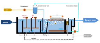 The raw water pre-treated with coagulant and flocculant enters the DAF tank. The DAF pump recycles supersaturated water by mixing water and high-pressure air in the dissolved air reactor (ADR). The bubbles cause suspended solids and oil to float to the surface of the water and form a froth layer. At the surface, a mechanical float removal device consisting of a scrapers travels over the DAF tank surface and pushes the froth over the beach plate into the scum collection channel.
The Air Dissolving Reactor (ADR)
According to Henry's law, the solubility of air in water is different under different pressures at different temperatures. The specific law can be seen in the diagram below.
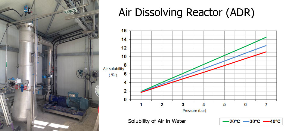
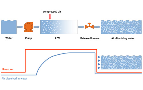
This continuous dissolution reaction will gradually reach a dynamic balance between the intake capacity and the thickness of the air cushion as the equipment runs for a long time. That is, as the intake capacity increases and the air cushion thickens, the influent will be able to Dissolve the gas more quickly, which in turn slows or reduces the further thickening of the air cushion layer, thereby maintaining the contact dissolution of the gas phase and the liquid phase in the ADR in a relatively stable state, which is favourable for the continuous high efficiency and stability of the dissolved gas reaction. The pressure in the ADR is maintained by a relief valve that also regulates the amount of pressurized water. The amount of gas in the ADR is adjusted to optimum gas saturation solubility to reach the best floatation effect.
|
No.
|
Project |
KWI |
Traditional |
|
1 |
Gas-water dissolution method |
Unique flow guiding device to accelerate dissolution |
ejector or padding |
|
2 |
Bubble uniformity |
Uniform |
Uneven |
|
3 |
Bubble utilization |
high |
low |
|
4 |
Pressure |
5-6bar |
2~4bar |
|
5 |
Dissolved gas residence time |
10~ 60s |
2~4min |
|
6 |
Dissolved air water saturation |
80%~90% |
50%~80% |
|
7 |
Recycle ratio |
15%~30% |
5%~20% |
|
8 |
Continuous running time |
10 years without maintenance |
0.5 years to 1 year |
|
9 |
Removal efficiency |
high |
low |
|
10 |
Turbidity |
Low, less than 3 NTU |
high |
|
11 |
Solidification rate of sludge |
3%~5% |
1%-2% |
|
12 |
Gas-solid ratio |
High |
low |
|
13 |
Chemical dosage |
low |
high |
|
14 |
Pollution situation |
Not easy to foul |
Easy to foul |
|
15 |
Bacterial |
No bacterial growth |
Filler breeding bacteria |
|
16 |
Volume |
small |
Big |
|
17 |
Technical content |
high |
low |
